Additional functionality
Warning
Attention! This functionality does not allow reprogrammingrestyled Sony radio tape recorder (central volume control on the radio is covered with black rubber compound)
This section contains features that may be requiredadvanced users, as well as the functionality that is quite specific and cannot be placed on any form by Ford brand accessories.
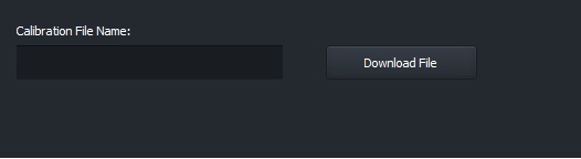
Downloading VBF files
Enter the file name and click the “Upload File” button. If a file with the given name exists on our server, it will be downloaded, unpacked and placed in the folder …\UCDS_V3\Downloads
Downloading VBF files
Functionality for Ford Sony ACM
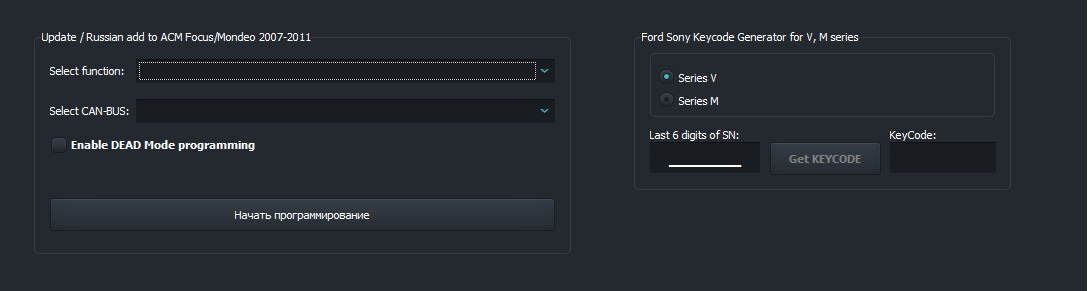
This section allows you to program Sony radios as the latest firmware, and with the possibility of Russification. Also availableThe function of generating a PIN code for unlocking the radio.
Sony ACM programming
Warning
Please note that for the Russification function of the radio, yourequires an active ODO license on the adapter!
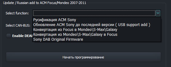
In the drop-down list, select the function you are interested in, select the CANBUS network on which the radio is located and press the “Start”buttoprogramming”
Working Sony ACM
Functional for programming Sony ACM
Note
Please note that the programming of the Sony radio tape recorders is installed on Ford Focus 2 cars \ Ford C-Max is carried out via the CAN bus PINS 3\11, and on cars Ford Mondeo 4 \ S-Max \ Galaxy on bus CAN PINS 1\8.
Sony ACM PIN Code Generator
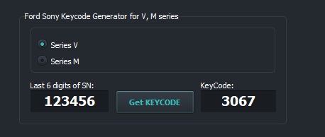
This functionality is designed to receive an unlock PIN codeSony radio with serial numbers starting with “M” and “V” Select serial number type by first letter, enter radio serial number and press “Get KEYCODE” button. Code for radio will be displayed in the corresponding window.
Sony ACM PIN Code Generator
Programming auto folding mirrors for a\m Focus 2 \**Kuga 1** \ C-Max
This functionality will add to the car the ability to auto-folding\unfolding side mirrors when arming\removing car is armed, both with a regular key and with an installed one alarm(if installed).
Warning
Attention! If your car has an not original car alarm with control of the central lock of the car through an additionally installed CAN BUS module - move alarm system to “Service” mode or full physical disabling of the alarm from the vehicle data bus - REQUIRED. Otherwise, the module programming procedure willviolated by the intervention of an abnormal alarm, the firmware of such a modulewithout physically disabling the alarm will be IMPOSSIBLE. Car LOSE the ability to close with a key. Glass control the car from the driver’s door will be IMPOSSIBLE until successful module programming! Be careful!
Note
Please note that after programming the function auto-fold is off. It is also necessary to ONE-TIME from the control switch on the driver’s door to cycle folding mirrors with their subsequent unfolding.
Activation\deactivation of auto folding mirrors is performed by to the following algorithm:
Turn IGN ON
Make sure the front windows are fully up\closed
Set mirror selector right\left to neutral
Clamp both front window control buttons as much as possible UP
Without releasing the front window controls, press the joystickmirror positioning key:
RIGHT**(looking towards the driver) - to **ACTIVATE the functionauto folding mirrors
LEFT**(looking towards glass) - for **OFF function auto folding mirrors
Note
This rather complicated sequence was introduced in order to avoid situations with accidental activationdeactivation of this feature.
Time and date setting via CANBUS
This functionality is intended for vehicles that have a standard the multimedia system has been replaced with an Android radio. In some cases, the radio cannot find out the time and date. For these situations, select the date and time, select the type of bus and press the “Submit” button time and date…”
Note
The command to set the date and time will be sent ONLY to the bus MM-CAN located on pin 1\8 of the car’s OBD connector.
CANBUS Data Analyzer
This section is intended for advanced users who understand what they are doing. Serves for a comprehensive analysis of connected CANBUS vehicle buses, determining data ID, their presence, period appearances in the bus, as well as data changes in all bus IDs at once and in each ID separately.
Setup connection
Adapter V5 can SIMultaneously receive data from THREE data buses, connected to pins 6\14, 3\11 and 1\8. In depending on your interests and needs, make the initial setting to connect to data buses. To do this, for EACH bus, if it is needed for learning, select its data rate and the type of IDs received from the data bus.
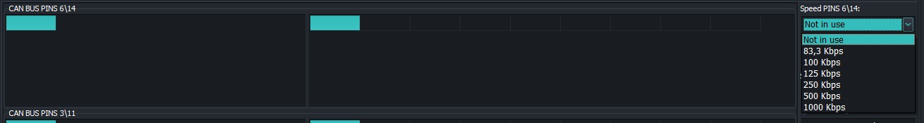
Data rate selection |
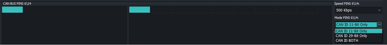
ID type selection |
Possible speed options: 83\100\125\250\500\1000Kbps
Mode options:
CAN ID 11-bit Only - packet reception mode ONLY with standard ID length 11 bits
CAN ID 29-bit Only - packet reception mode ONLY with extended ID long 29 bits
** CAN ID BOTH** - receive packets at the same time as standard long (11 bits) and extended (29 bits)
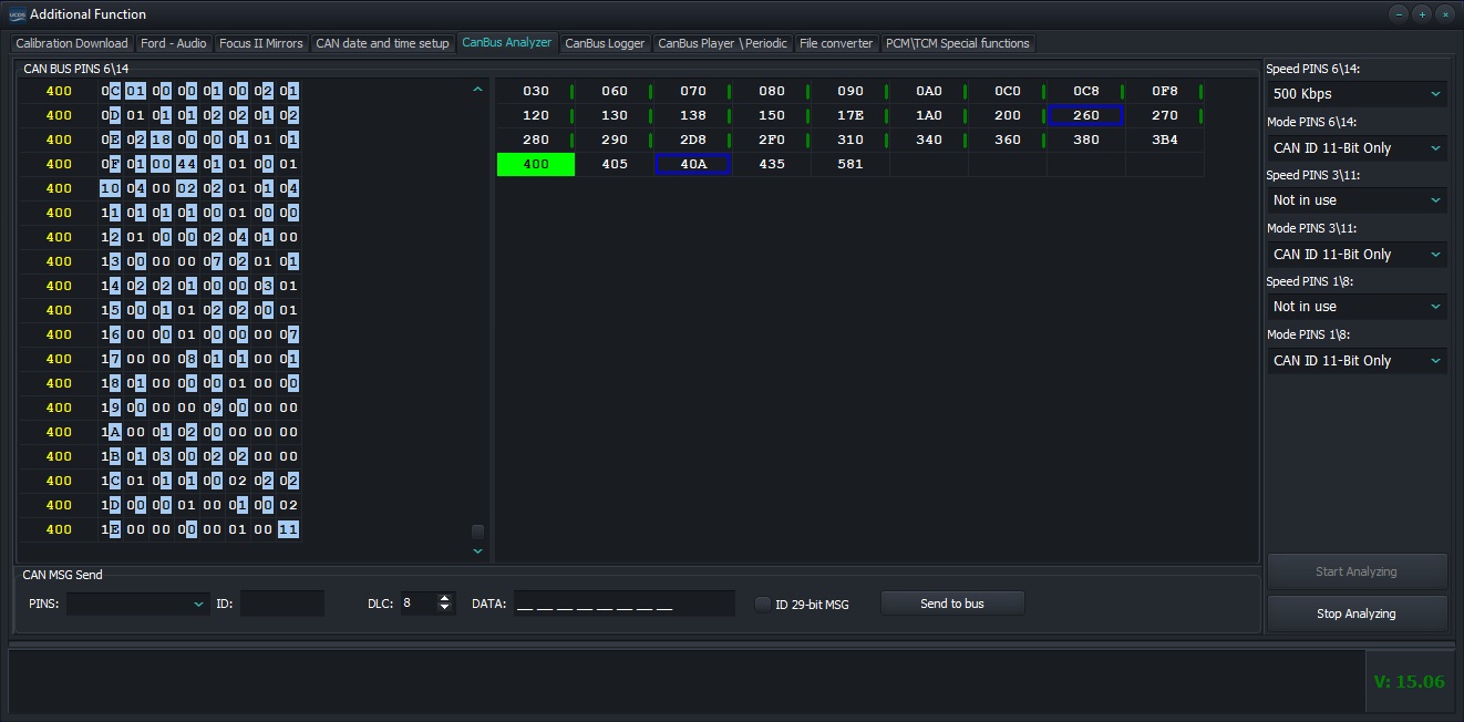
After setting, click “Start Analysis” button.
Main screen
This screen displays ALL received IDs on the connected bus data that are arranged in ascending order. This displays information about how often the data arrives, and whether the data changes with each subsequent arrival of the command EACH ID in relation to previous. The choice of IDs of interest is made by clicking the left mouse button by ID in the table - ID will be highlighted in green. At the same time, in the left window only selected IDs will be displayed. Right click on The table ID will remove it from the analysis. This ID will be grayed out.
CANBUS analyzer operating mode
Possible types of ID display in the table:

|
ID received one-time, no data at the moment |

|
ID selected for detailed analysis and display |

|
Received data on the bus with the given ID |

|
ID came with CHANGES in data field |

|
ID 29-bit |
Warning
Attention! A large selection of IDs requires increased resources of your PC.
The left window displays data for the selected IDs in the table. Each the command is displayed with highlighted tetrads of each byte, where a bit change occurred. There is a context window for this window menu that is invoked by the right mouse button and allows you to save current log to file, clear window, and enable or disable mode of highlighting changes in received data bytes.
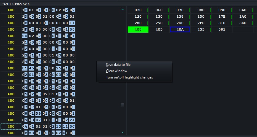
Data for selected IDs with change highlighting and context menu
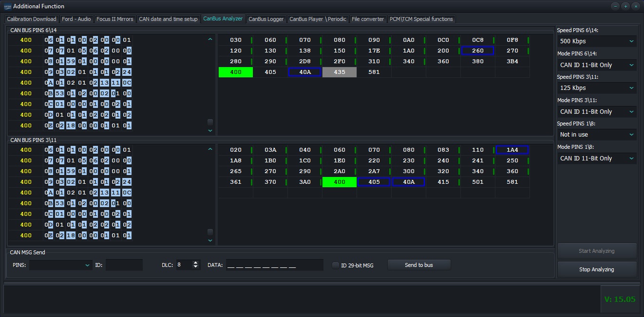
Working with two buses at the same time
Sending commands to CANBUS
It is possible to send single commands to the data bus, in analysis process. Select the tire you need, fill in the ID field, DLC, the field with data and click “Send to Bus”

Sending commands to the data bus
Warning
Attention! If you try to send a command to the data bus, to which you have not connected, or if the ID type mode is violated commands (trying to send a 29-bit command when set to 11-bit only or vice versa), then when you try to send a command, you will receive a message about mistake!
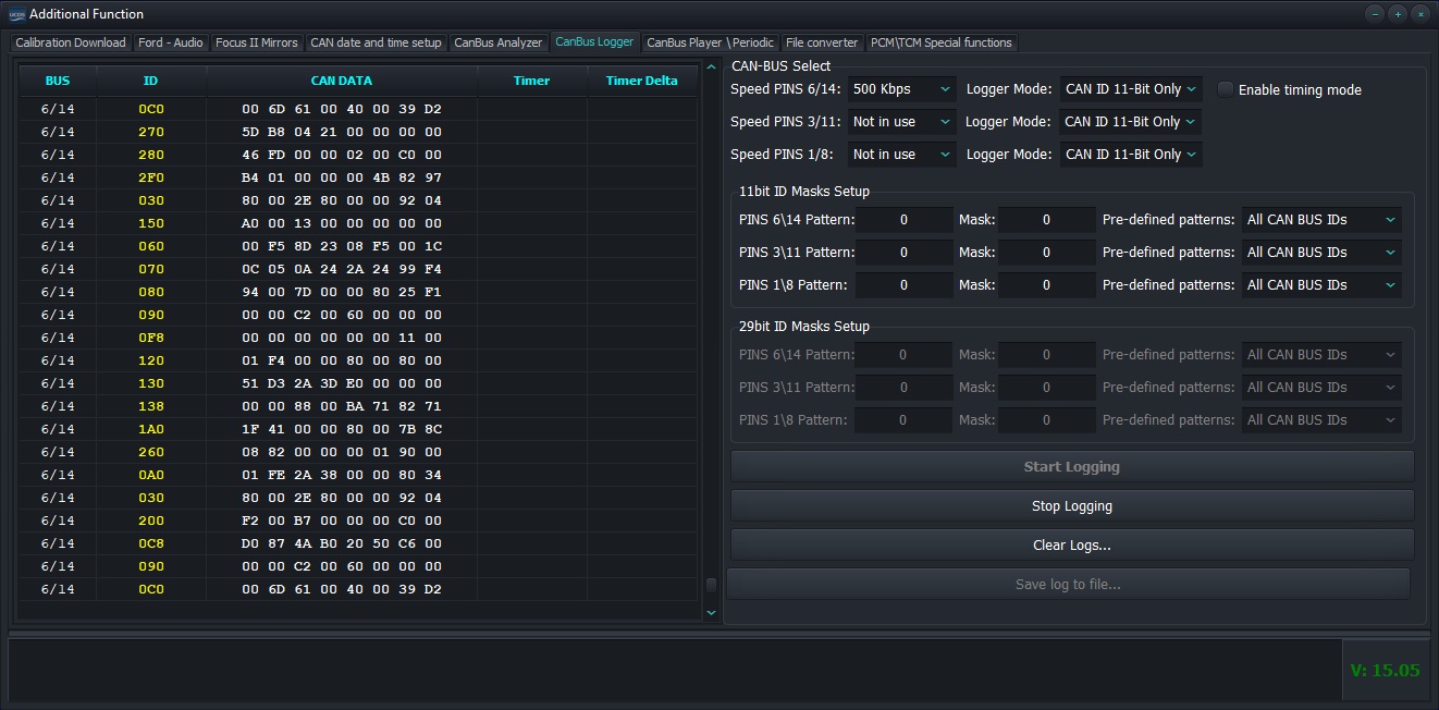
CANBUS data logger
This section is a functionality that allows you to shoot for Further study of the logs from the connected CANBUS data buses.
Setup connection
Configuring the connection to the CANBUS data buses is almost identical configuration under “CANBUS Data Bus Analyzer”, except the fact that the user is given the opportunity to independently configure receiving data from CANBUS buses through self-configuration patterns and masks for received IDs from data buses.
Setting up masks and patterns
The user is offered three options for setting masks and patterns for getting ID from CANBUS data buses
Accept ALL IDs from data bus
Only accept diagnostic IDs (7xx) from data bus
Set your own pattern and masks for receiving data
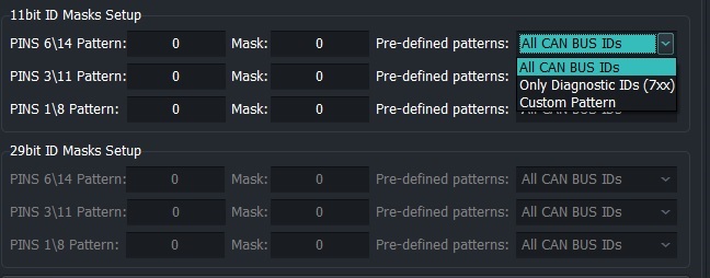
Setting patterns and masks
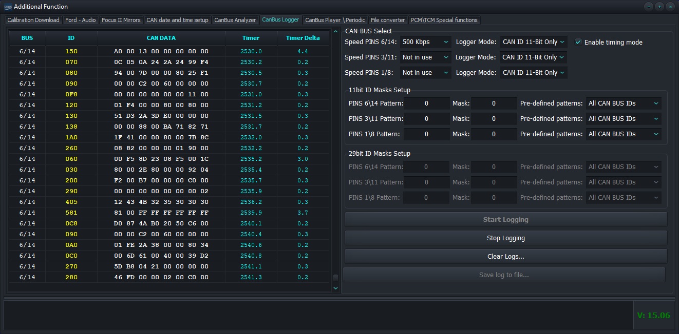
Timing mode
Enabling this option will display the time the command was received from the moment of start, as well as displaying “delta” time between teams, in the order they were received. This information will be displayed in the last two columns “Timer” and “Timer Delta”.
Logging without timeout |
Logging with timeout |
Working with data
In the process of receiving data from CANBUS, it is possible to view in detail received data, scroll the list up\down. To do this, click left mouse button on the data field. The list will stop and you will see the ability to scroll data in any direction right at the time of receiving new commands from connected CANBUS buses. List management produced by keyboard cursors, PgUp\PgDown keys, mouse wheel, as well as combinations Ctrl+PgUp and Ctrl+PgDown.The combination Ctrl+PgDown will make the list “run” when getting new data.
Note
Clearing the window with data, as well as saving data to a file is possible ONLY after the data collection process is stopped.
Playback logs to CANBUS
This section allows you to play in advance saved logs to the buses connected to the adapter.
Note
Please note that the UCDS software will only be able to reproduce logs pre-recorded with the help of UCDS software. Logs created Unfortunately, it is not supported by any third-party programs.
Playback Setting
Select the saved log file. Select the speed mode for the appropriate adapter pins. Specify the required pause between each frame, which will hold the adapter and click “Play log files”.
Periodic messages in CANBUS
This functionality allows you to create a list of commands with their ID, data and period, for their subsequent sending to CANBUS buses.
Setting up a connection and adding messages
Select the required bus speeds on the corresponding adapter pins.Press “Connect to buses” button. Add command to list. To do this:
Specify CANBUS type
Specify ID
Specify DLC (command length)
Specify the period for sending the command (minimum period 5ms)
Enter command data
Click the button “Add periodic message”
The command will be added to the table. Start sending periodic messages are done by checking the “tick” in the first column. Removing a command from the list is done by clicking on the button “Remove” in the “Service” column of the corresponding command

Adding a Periodic Command to the List
Note
If the periodic message started successfully, in the “STATUS” column the message “Executed” appears, or “Fail to start” if not any conditions for tire tuning have been met. Please note that ONLY if the data buses, their speeds and physical connection of the adapter to the data buses will increase value in column “COUNT”.

Example of successfully running a periodic command
Loading and saving tables with messages
To optimize performance, it is possible to load\save table of periodic messages from\to file(s). To do this, in the buttons “Load periodic table from file” and “Save “ are intended periodic table to file”.
VBF -> BIN File Converter
This section is for converting .VBF files to a file .BIN format Recommended for use exclusively for “advanced” users who understand what “organization” is memory” and “address space”.
Opening a file and correcting addresses
Select the .VBF file of interest. The program will analyze the data blocks and will show the number of blocks, their size, as well as the address in memory “Offset”, where the data block is planned to be written. To the user given the opportunity to independently specify which offset “Offset” in the output .BIN file must be placed every concrete block.
Warning
Attention! The program does not perform any heuristic analysis to understand where exactly you need to put each specific block of data. You need understand that all .VBF files are for DIFFERENT processors, installed in modules, which in turn have DIFFERENT memory organization. For some files, you don’t have to produce correction “Offset” for each block, and in some it will be necessary do for everyone. User is supposed to have a view about all this.
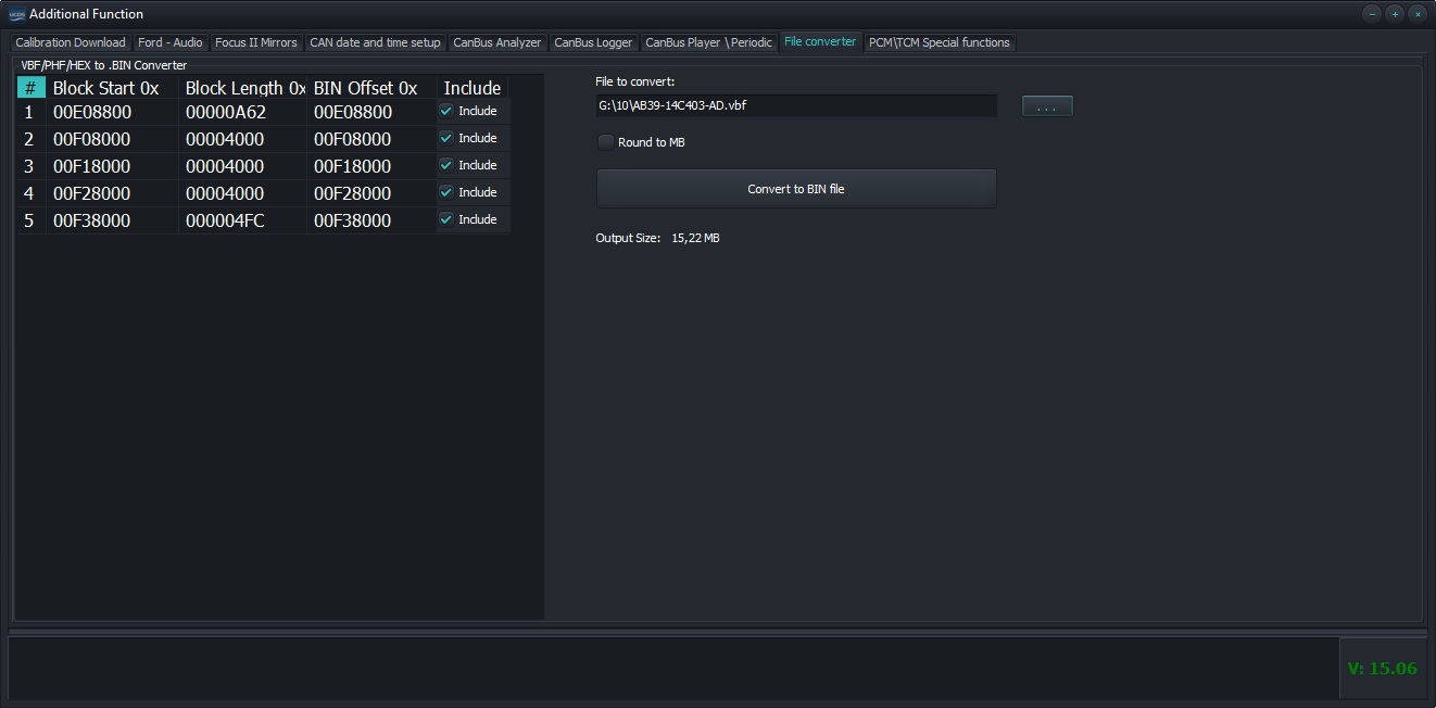
Display uploaded file
For each block, there is an option to exclude it from being added to output .BIN file by turning\off option “Include”. In some cases, it may be necessary to round output file to the size of a multiple of 1MB upwards, which is done by including the option “Round to MB”.
Special functions for PCM\TCM
This partition allows read\write areas of FLASH\EEPROM supported blocks, using own loader, via data busCANBUS.
Warning
Warning! This section is STRONGLY not recommended for users, who have no experience in these actions. Unskillful actions, wrong entry “garbage data” can result in FULL disabling the unit, the return of which to a working state can be IMPOSSIBLE WITHOUT BLOCK OPENING.
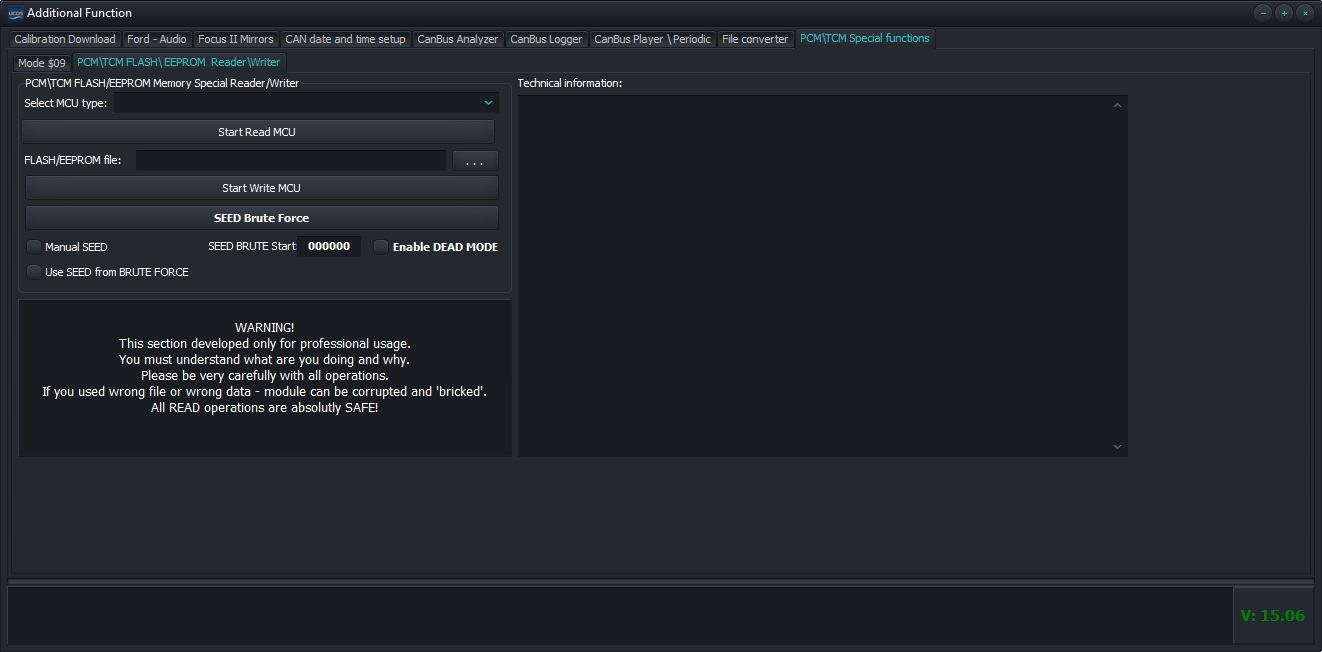
Special functions for working with PCM\TCM units